DPC speaker's dummy guide into arduino
Tagged with:
This year the DPC (and DMC) bought all speakers one of the coolest gifts I’ve ever got (or seen) for speakers: an Arduino. During the speaker dinner, a lot of people were a bit confused on how it was and works. So this post is for all of those, plus everybody else who wants to get involved in Arduino, programming and some electronics. It really is fun!
Don’t get me wrong, I don’t know much about electronics. To be honest, it scares me a bit in how complex things can actually be build by it, but in all fairness, the basics are pretty easy to understand. LUCKILY, this isn’t a guide in how electronics works, since that is all boring stuff you can find on other pages, but how to get your arduino up and running in no time!
Requirements:
- Your arduino (uno)
- A USB type B printer cable. Yes, that’s how universal USB actually is.. there are a gazillion (and counting) different types. We need the type that normally is used in printers, so get your printer and yank out the cable. It probably fit.
Manual:
- Add the cable to your laptop and to the Arduino.
- Done
Yes, it is that easy. Once you have hooked on your arduino the your computer, you will see a light going on and another light blinking. Congratulations, your arduino processor is currently busy running it’s initial program (the karate-kid wax-on-wax-off program).
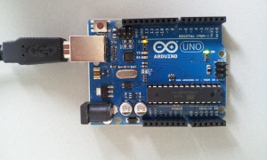
Now, a really quick intro on the arduino. The arduino is nothing more than a simple circuit-board that holds a processor (the big black long thingie, as we technicians like to call it), and on the sides you see some input and output “holes”. These holes are marked with some labels like “IOREF”, “RESET”, “A0” to “A5” and “DIGITAL0” to “DIGITAL13”. As long as you don’t have any additional materials besides your usb-cable and arduino, these are pretty much useless.
As you can see as well, there is a small button next to the USB port which is the reset button. It literally resets the arduino so if something goes wrong, you can reset your arduino by hitting this button. Also there is a “on”-led, which shows you that the arduino is turned on, and some additional leds, like the blinking one marked “L” (for LED), and two additional ones called “TX” and “RX”. This stands for transieve and receive (notice that DIGITAL0 and DIGITAL1 slot also got a TX and RX? Those are actually connected. So if you put power to those leds, you actually put power on those ports as well, and vice versa..
Since the LEDS are the only things we can play with, without additional stuff, let’s focus on those ones!
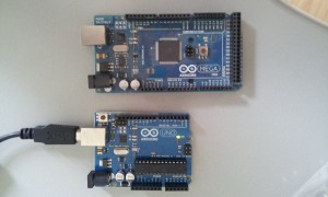
Oh, one more thing. If you happen to enjoy working with the arduino, there are other versions as well. As you can see, I have an additional arduino MEGA, which has got more inputs and outputs. Also the actual CPU is a bit more advanced.
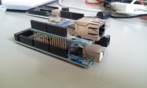
Another cool thing: you can actually “extend” your arduino with extension boards. For instance, this is an extension board for connecting your arduino up to an Ethernet network, and thus add the possibility to connect it to the internet. You just stick the extension board onto your arduino and you’re up and running. That’s right: you can actually get your arduino running on the interwebz! Plus this one actually has an SDcard holder on board, which means we can do things with SDcards too (like reading/writing files)..
Back to our arduino. Let’s play around with our LEDs. This means we must program the processor into actually doing stuff. Luckily, this is pretty easy with help of the free software that you can download. Download this software and run it. It should come up with an editor. Add the following code:
void setup() {
  pinMode(13, OUTPUT);
}

void loop() {
  digitalWrite(13, HIGH);
  delay(200);
  digitalWrite(13, LOW);
  delay(200);
}
This will tell the arduino that pin 13 is an output. Pin 13 is also the pin that happens to be connected to our L-led. The loop() method is nothing more than telling the arduino to put a “high” voltage onto the pin, meaning the light will go on. Wait for 200 milliseconds, put the voltage down again, so the led will turn off, and wait for 200 milliseconds. This will be repeated continuously.
Make sure you have set the correct board in your “Tools | Board” menu, that you have the correct USB port, and press “upload”. This will compile and upload the file to your arduino, so it will run (a fast blinking light). If we had an external power source, we could remove the USB cable, and the arduino would run on itself.
Next time I will show you a bit more on the things you can do, but this would probably mean we need to get some electronic stuff. Don’t worry though, for a few euro’s you probably can get more than enough to keep you busy for a long time.


